Example 3.3
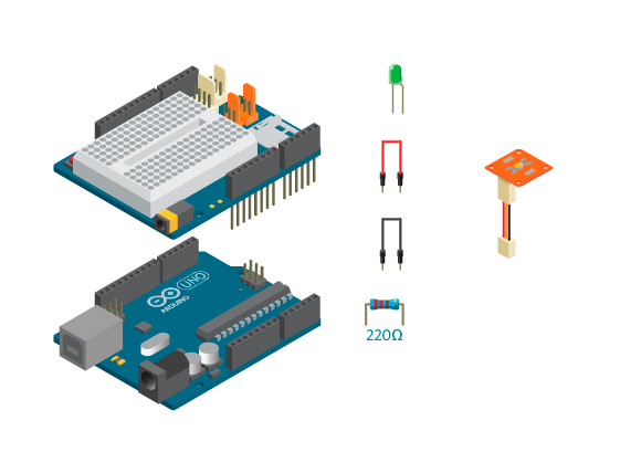
In this example, you will change the light intensity of an LED depending on the readings from an LDR.
Materials

- 1 Arduino Uno board
- 1 Education Shield
- 1 TinkerKit LDR
- 1 LED
- 1 220 ohm resistor
- 1 TinkerKit wire
- 2 jumper wires
Instructions

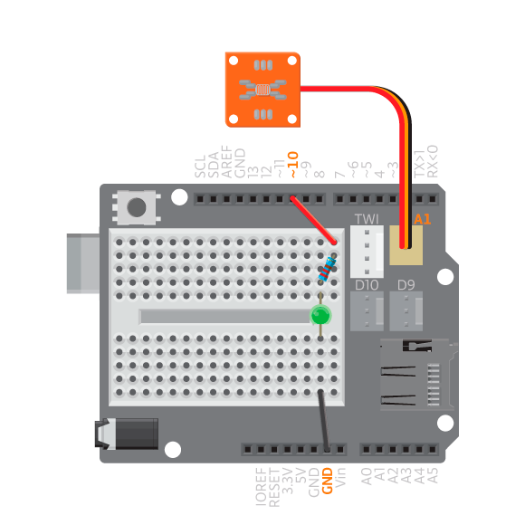
- Attach the shield onto the top of the Arduino board.
- Connect the LED across the breadboard gap.
- Connect a 220 ohm resistor to digital pin 10 using a jumper wire. Connect the resistor to the long leg of the LED.
- Connect the short leg of the LED to GND using a jumper wire.
- Connect the TinkerKit LDR to analog TinkerKit connector, A1.
- Upload the following code:
Result
You should now cover the LED with your hand or expose it to bright light. The LED should darken when the LDR is covered, and shine bright when the LDR is exposed to light.
New commands
map(value, fromLow, fromHigh, toLow, toHigh): Re-mapsvaluefrom one range to another.fromLowtofromHighis the range you want to re-map from, andtoLowtotoHighis the range you want to re-map to.
How it works
- Two variables are declared,
ledPinandldrPin. - Nothing happens in
setup(). - In
loop(), the variableldrValueis declared to hold the read analog value on pin A1. This value can range from 0 to 1023, which is a range that is too big to be used to write an analog value to a pin. - The variable
ledValueis declared to hold the remapped value ofldrValue. This value will range from 0 to 255. WhenldrValue= 0,ledValue= 0, whenldrValue= 1023,ledValue= 255, whenldrValue= 512,ledValue= 127, etc.. - An analog value is written to pin 10 using
ledValue. - The program pauses for 10 milliseconds.
loop()continues to loop.
Learn by doing
- Make the automatic lamp previously mentioned. When the LDR reading is lower than a certain value or threshold, the light turns on. Above that value, it turns off. Use an LED to simulate a lamp.
- Use the LDR to generate sound with a piezo. Remember to map the values correctly.
Sensor calibration
An LDR is a sensor heavily influenced by its environment. A project using LDRs will work differently in different places because the amount of light present in different settings. You will have to calibrate your LDR depending on the location to ensure that it works.
Take the automatic lamp that turns on when it gets dark. Say you want to trigger it when a piece of paper covers the LDR.
You will need to experiment with different thresholds so that it triggers with the piece of paper. Once you figure out the threshold, move the LDR under the table and try to see if the paper will trigger it there.
Likely, it will not work and that is the problem. The paper does not change the LDR reading that much when there is already too little light, such as under the table. The way to solve this is to be able to change the threshold dynamically.
Example 3.4
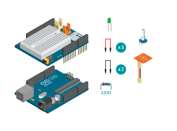
In this example, you will use an LDR as a switch and turn an LED on or off depending on the readings. You will use a potentiometer to set the switch threshold.
Materials

- 1 Arduino Uno board
- 1 Education Shield
- 1 TinkerKit LDR
- 1 potentiometer
- 1 LED
- 1 220 ohm resistor
- 1 TinkerKit wire
- 2 black jumper wires
- 3 colored jumper wires
Instructions

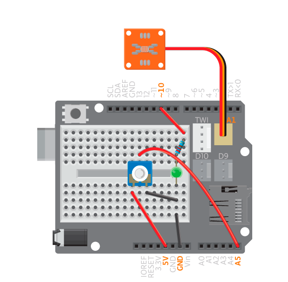
- Keep the circuit from the previous example, and add a potentiometer.
- Connect the potentiometer to the breadboard.
- Connect the single potentiometer pin to analog pin A5, and the other two to 5V and GND using jumper wires.
- Upload the following code:
Result
You should now cover the LDR and see if the LED turns on. If it does not, or if it is on all the time, you should turn the potentiometer until you get a threshold value that works.
How it works
- The variable
potPinis added to hold the number of the analog pin to which the potentiometer is connected. - Because you are using the LED as a digital actuator in this example, pin 10 is configured as an output in
setup(). - In
loop()the variableldrValueis declared to hold the read analog value on pin A1. - The variable
thresholdis declared to hold the read analog value from pin A5. - If
ldrValueis bigger thanthreshold, the LED is turned off. - If
ldrValueis not bigger thanthreshold, the LED is turned on.