In the world of Arduino, “shields” are boards that can be plugged on top of the Arduino extending its capabilities. Education shield is designed for CTC and has a collection of features that are easy to use.

- Reset button. When pressed the program uploaded to the Arduino board is restarted.
- Breadboard. Read more about the breadboard here.
- Digital input and output pins. Directly connected to the digital pins on the Arduino. You use these pins when you are using digital sensors or actuators. Some of these pins are PWM pins. They are directly connected to the PWM pins on the Arduino. Use these when you want to make analog outputs.
- A1 TinkerKit port. Connected to analog pin A1. If you are using a sensor on this port you cannot use the analog pin A1 for something else.
- D9 and D10. These are digital TinkerKit ports. They are connected to digital pin 9 and 10 so if you’ve connected anything D9 or D10 you cannot connect another thing to digital pin 9 or 10.
- Speaker plug. You can use a speaker plug to plug in here. This is connected to digital pin 11 so do not use this pin for other things while a speaker is plugged in here.
- Ground and power pins.
- Analog input pins. These pins are connected to Arduinos analog pins. You use these with your analog sensors.
- SD card port is used for plugging a microSD card. Push in the card until it makes a “Click” sound and stucks. If you want to get it out, push the card first so it makes a “Click” sound and gets loose, then you can pull it out. The micro SD card reader is connected to digital pins 10 to 13.
Keep in mind:
- Avoid using analog A4 and A5. Because of components on the shield connected to these pins (there are pull-up resistors to enable connecting to some sensors), they can behave a bit weird at times.
- Do not use digital pins 10 to 13 when using the micro SD card reader.
- Digital pins 9 to 13 cannot be used for capacitive sensors
- Digital pin 9, 10; analog pin A1 are connected to TinkerKit ports, so if you’re using the TinkerKit ports, don’t use the corresponding pins.
- Digital pin 11 is connected to the audio socket, when using a speaker don’t use the corresponding digital pin.
TinkerKit connectors
The TinkerKit ports are used for all the TinkerKit components, as well as some 3-pin components(servos in our case). TinkerKit components can be plugged in without any problems, as the plastic parts limit how they can be plugged.
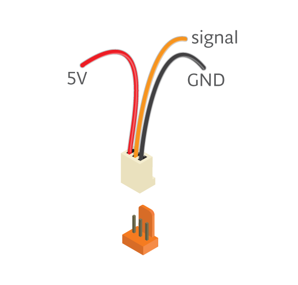
If you’re trying to connect servos or other 3-pin components, be sure about the direction of the connector so that GND is connected to GND, 5V to 5V and signal to signal.The color of a TinkerKit wire helps you remember it: red means power, orange means signal, and black means GND. Technically you can connect TinkerKit Components without TinkerKit ports, as long as you plug the wires to the right pins.
