The same way you can write HIGH or LOW to an Arduino digital pin, you can read a state generated by a digital sensor connected to it. Digital inputs can, just like digital outputs, only have two states.
Example 2.7
A single jumper will demonstrate the basic theory behind digital inputs. You will write a program that will turn the on-board LED on or off, depending on the reading from the digital pin where the jumper wire is connected.
Materials

- 1 Arduino Uno board
- 1 jumper wire
Instructions

- Connect a jumper wire to digital pin 5.
- Upload the following code:
Result
You should now switch between connecting the loose end of the jumper wire to 5V and GND. When connected to 5V the on-board LED should turn on, when connected to GND the LED should turn off. Note that it will not work perfectly.
New commands
pinMode(pinNumber, INPUT): configures the digital pinpinNumberto behave as an input.digitalRead( pinNumber): reads the value from the digital pinpinNumber, eitherHIGHorLOW.
Repetition:
if( test ){ statements }: Checks iftestis true or false. If true, thestatementsinside the curly brackets are executed. If false the program jumps to and executes the code after the curly brackets.value1 == value2: Comparesvalue1andvalue2. If the values are equal it returns true (1), if they are not equal it returns false (0). The double equal sign is called an operator.
How it works
- Two variables are declared,
ledPinandinputPin.ledPinholds the value 13, andinputPinthe value 5. - In
setup(), pin 13 is configured as an output and pin 5 is configured as an input. - In
loop(), pin 5’s state is read, and simultaneously checked if it is equal toHIGH. - If the wire is connected to 5V the reading is
HIGH, and the LED is turned on by writingHIGHto pin 13. - If the wire is connected to GND the reading is
LOW, and the LED is turned off by writingLOWto pin 13. loop()continues to loop, which means that the state on pin 5 is checked continuously.
Button
A single jumper wire might be a good way to explain the theory behind digital inputs, but it is not a reliable input for your projects. It is better to introduce you to the button. With an Arduino, you can read two different states from a button; HIGH or LOW.
In the next example you will use a TinkerKit button. TinkerKit components makes it easier for you to make circuits because they already are small circuits with the electronic components needed, such as resistors.
Example 2.8
This example does the same thing as the previous one, but instead of using a jumper wire as input, you will use a TinkerKit button.
Materials

- 1 Arduino Uno board
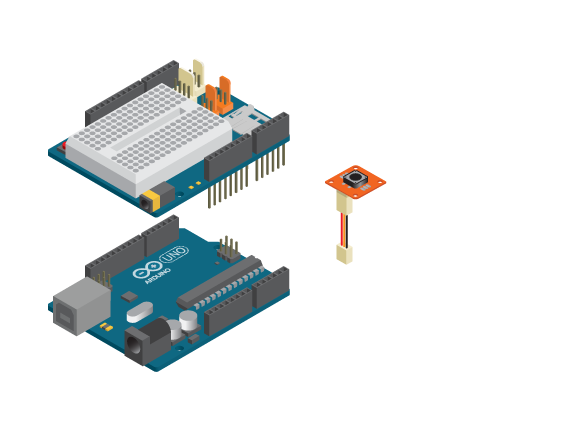
- 1 Education Shield
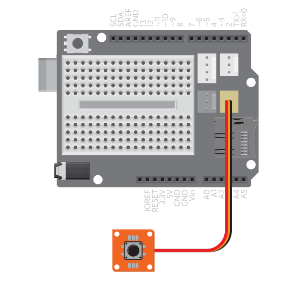
- 1 TinkerKit button
- 1 TinkerKit wire
Instructions

- Attach the shield onto the top of the Arduino board.
- Connect the TinkerKit button to D9 using the TinkerKit wire.
- Upload the following code:
Result
You should now push the button. The LED should turn on when the button is pushed, and turn off when the button is released.
How it works
- In this example
inputPinholds the value 9, the number of the digital pin to which the TinkrKit button is connected. - In
setup(), pin 13 is configured as an output and pin 9 is configured as an input. - In
loop(), pin 9s state is read, and simultaneously checked to beHIGH. - If the button is pushed, the reading is
HIGHand the LED is turned on. - If the button is released, the reading is
LOWand the LED is turned off. loop()continues to loop, which means that the state on pin 9 is checked continuously.
Learn by doing
- Write a program that plays a sound when you push a button.
- Add an LED that blinks when the button is pushed.