Come on lucky number! Use this digital die next time you play a board game.
You “throw” the die by shaking a tilt sensor. The LEDs will cycle through different numbers, slowing down until it finally stops and reveals the number.
Materials
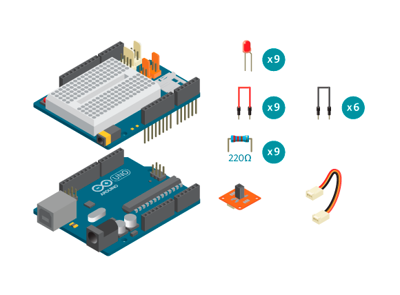
- 1 Arduino Uno board
- 1 Education Shield
- 1 TinkerKit tilt switch
- 9 LEDs
- 9 220 ohm resistors
- 1 TinkerKit wire
- 6 black jumper wires
- 9 colored jumper wires
Instructions
Code
Find the code in File>Examples>EducationShield>Block2-Sports>Projects>DigitalDie
How it works
- The EducationShield library is included.
- The LED variables are declared,
pinCountandledPins[]. - The TiltSwitch object is declared,
ts. - The die patterns are defined in a two dimensional array,
dice[6][9]. A die has 6 different sides, and on each side there are 9 potential spots for dots. - The die patterns are defined in a way to make it easy to visualize. In each pattern (each die side) there are nine zeros and ones. A 1 represents an LED turned on (a dot), and a 0 represents an LED turned off (blank)
- The variable
waitTimeis declared to hold the time in milliseconds to wait between the change of the pattern displayed. - In
setup(), the led pins are configured as outputs. - The tilt switch object is initialized.
- The random number generator is initialized.
- In
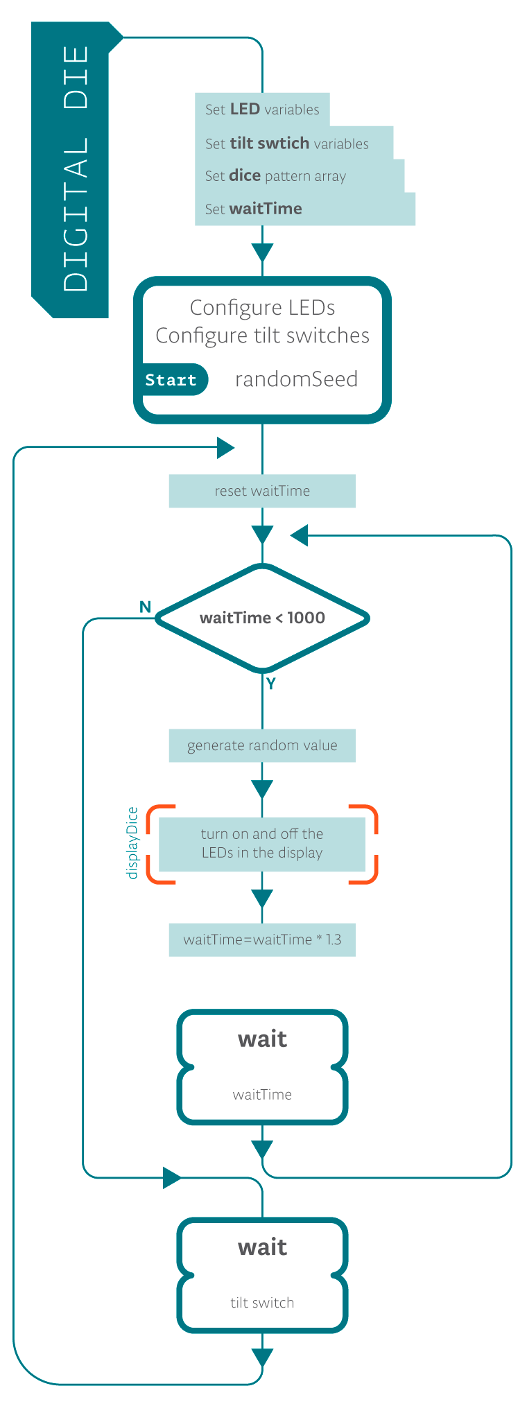
loop(),waitTimeis set to be equal to 2. - While
waitTimeis less than 1000, the following happens. - The variable
valueis declared and assigned a random value between 0 and 6. valueis passed to the functiondisplayDice()and the program jumps to that function.- In
displayDice(), a for loop loops through the LEDs and turns them on or off according to the patterns indice[][]. Whenvalueis equal to 2, the 9 zeros and ones ofdice[2][](the pattern that shows 3) will be looped through. - The program jumps back to the while loop.
waitTimeis increased by being multiplied with 1.3. This means that the 25th time the while loop runs,waitTimewill be more than 1000.- The program pauses for as many milliseconds as the value of
waitTime. - If
waitTimeis less than 1000, the while loop keeps looping, displaying the next randomly chosen pattern. - When
waitTimefinally is not less than 1000, the program leaves the while loop. - The program pauses until the tilt switch is pressed, or tilted.
loop()continues to loop.
Troubleshooting
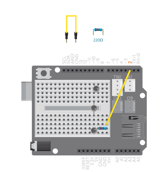
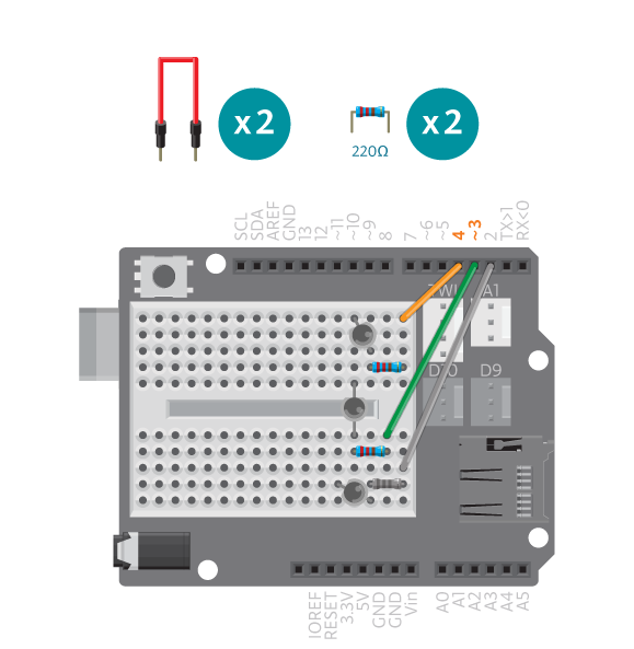
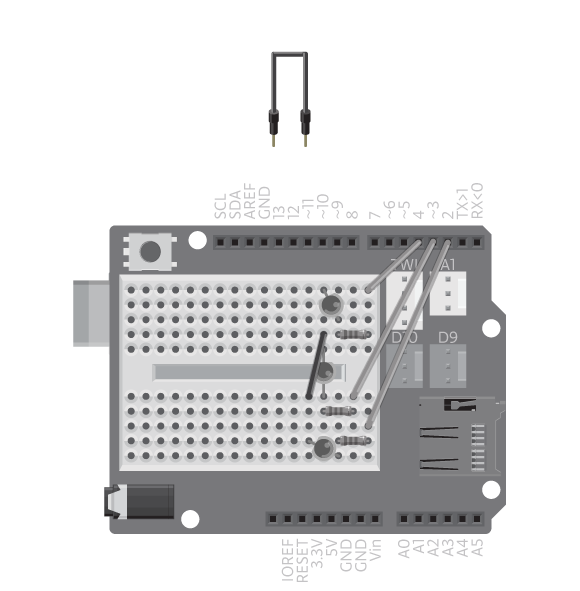
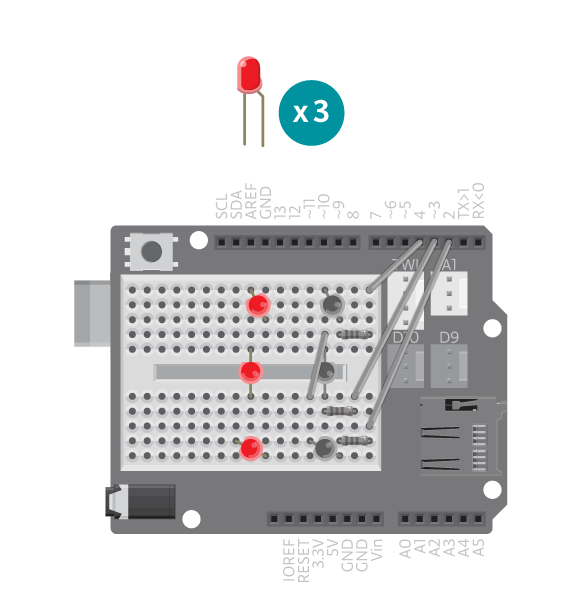
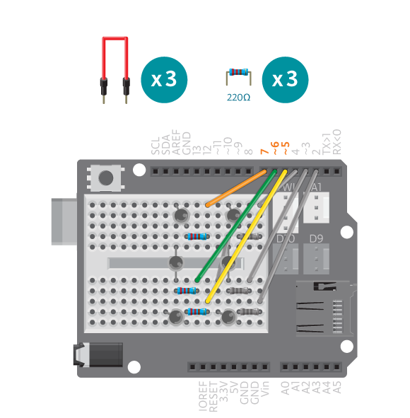
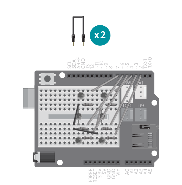
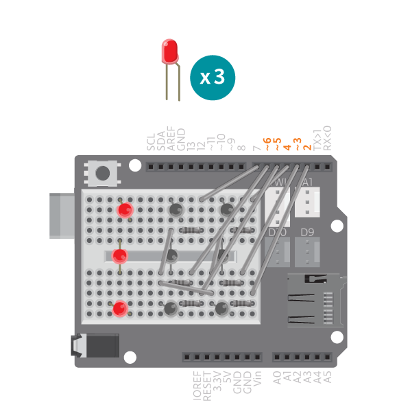
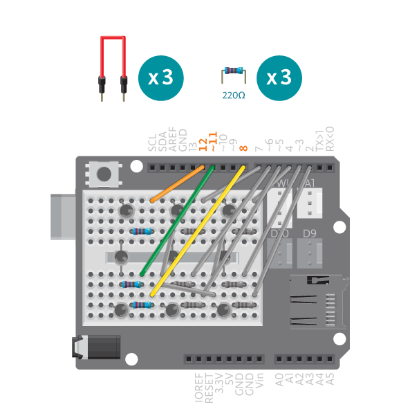
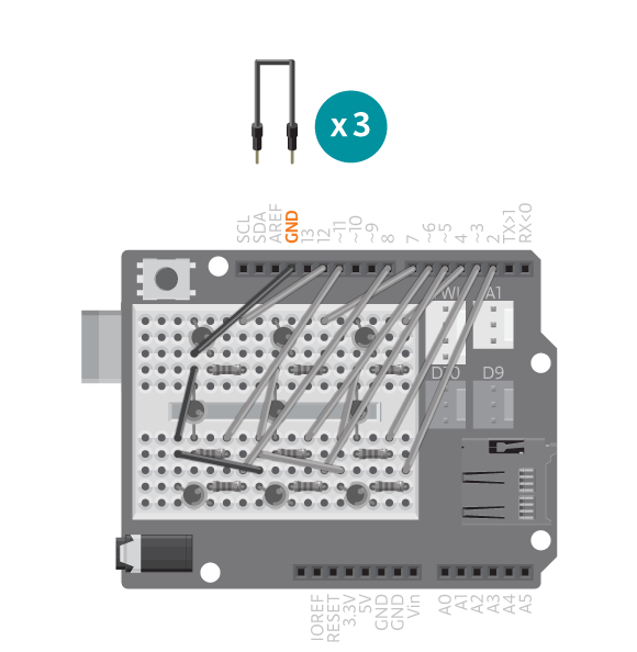
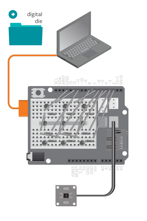
- If the die does not show the correct combinations of turned on LEDs, refer to the illustrations and double check all your connections. Make sure the shield and jumper wires are firmly connected. Check the LED polarities to make sure they are consistent and properly wired.
- If your tilt switch is not working correctly, make sure that it is in an upright position when the die is still “rolling”. Check the reference for debugging the tilt switch.
Learn by doing
- Change the patterns: make the LEDs display something else.
- Build a case: Use a 9V battery to power the Arduino and design a case so that you can simply shake the box to have it “roll the die”.


